| [ Home ] |
| [ Technology ] |
| [ Funding ] |
| [ News Releases ] |
| [ Upcoming Presentation ] |
| [ Employment Opportunities ] |
| [ Contact Us ] |
Spyder Technology
Publications relevant to Spyder technology:
Lebl, M. (2000) New technique for high-throughput synthesis of peptides, peptidomimetics and nonpeptide small organic molecule arrrays. In G.B. Fields, J.P. Tam & G. Barany (Eds.), Peptides for the New Millennium. (pp. 164-166). Kluwer Academic Publisher, Dordrecht.
Lebl, M., Ma, J., Pires, J., Dooley, C. & Houghten, R.A. (2000) Rapid parallel synthesis of 584 betides, peptides composed largely of beta-amino acids with side-chains not found in natural peptides. In G.B. Fields, J.P. Tam & G. Barany (Eds.), Peptides for the New Millennium. (pp. 174-175). Kluwer Academic Publisher, Dordrecht.
Lebl, M., Krchnak, V., Ibrahim, G., Pires, J., Burger, C., Ni, Y., Chen, Y., Podue, D., Mudra, P., Pokorny, V., Poncar, P., & Zenisek, K. (1999) Solid-phase synthesis of large tetrahydroisoquinolinone arrays by two different approaches. Synthesis-Stuttgart, 1971-1978.
Lebl, M., Pires, J., Poncar, P., & Pokorny, V. (1999) Evaluation of gaseous hydrogen fluoride as a convenient reagent for parallel cleavage from the solid support. Journal of Combinatorial Chemistry, 1, 474-479. http://pubs.acs.org/journals/jcchff/index.html).
Lebl, M. (1999) New Technique for High-Throughput Synthesis. Bioorg. Med. Chem. Letters, 9, 1305-1310.
Lebl, M. (1998) A New Approach to Automated Solid phase Synthesis Based on Centrifugation of Tilted Plates. Journal of the Association of Laboratory Automation, 3, 59-61.
Eichler, J., Houghten, R.A., & Lebl, M. (1996) Inclusion volume solid-phase peptide synthesis. J. Peptide Sci., 2, 240-244.
Pokorny, V., Mudra, P., Jehnicka, J., Zenisek, K., Pavlík, M., Voburka, Z., Rinnová, M., Stierandová, A., Lucka, A.W., Eichler, J., Houghten, R.A. & Lebl, M. (1994) Compas 242. New type of multiple peptide synthesizer utilizing cotton and tea bag technology. In R. Epton (Ed.), Innovation and Perspectives in Solid Phase Synthesis. (pp. 643-648). Mayflower Worldwide Limited, Birmingham.
Lebl, M., Stierandová, A., Eichler, J., Pátek, M., Pokorny, V., Jehnicka, J., Mudra, P., Zenisek, K. & Kalousek, J. (1992) An automated multiple solid phase peptide synthesizer utilizing cotton as a carrier. In R. Epton (Ed.), Innovation and Perspectives in Solid Phase Peptide Synthesis. (pp. 251-257). Intercept Limited, Andover.
Spyder Technology: A New Approach to Automated Solid Phase Synthesis Based on Centrifugation of Tilted Plates
Abstract: High throughput solid phase synthesis can be performed with application of the centrifugation based liquid removal. This technique uses readily available standard microtiterplates and eliminates filtration step. It is therefore applicable to simultaneous processing of unlimited number of reaction compartments.
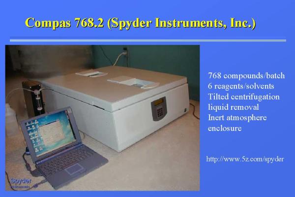 Figure 1 |
Basic problem of solid phase synthesis is parallel separation of liquid and solid phases. Commercial solid phase synthesizers utilize filtration as the principle for separation of solid and liquid phase. Filtration can lead to significant complications, especially in the case of multiple synthesizers, since clogging of one vessel can result in overflowing of this particular vessel during the next solvent addition and distribution of the solid support from this vessel into neighboring ones.
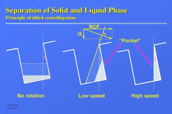 Figure 2 |
 Figure 3 |
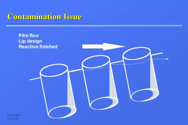 Figure 4 |
Situation of wells in microtiterplates placed on the perimeter of the centrifuge depends on the distance of the individual well from the axis of rotation. The volume of the "pocket" created by centrifugation in the wells closer to the axis is bigger than the volume of the pocket created in the wells more distant from the center of rotation. The volume of the pocket is not as important as the ratio of volumes of pockets in different wells of the microtiterplate. This ratio depends on the dimension of the centrifuge rotor, speed of the rotation, and the tilt of a plate. Wells placed on a rotor of very large diameter, or rotor spun very
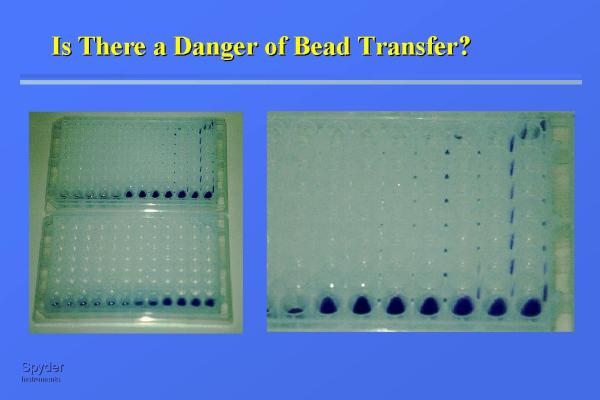 Figure 5 |
 Figure 6 |
If drilling of holes into inert material would create the array of wells, the liquid expelled from one well would inadvertently enter another well placed closer to the perimeter of the centrifuge. However, 96 well shallow microtiterplate is actually composed of 96 small cylinders attached to a flat polypropylene sheet and connected by a thin "rib", creating thus an array of 96 round wells plus 117 interwell spaces. The liquid expelled by centrifugal force from one well comes into the interwell space, flies
 Figure 7 |
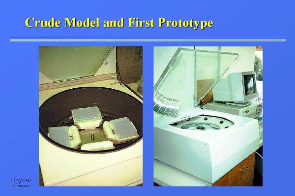 Figure8 |
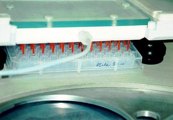 Figure 9 |
The first experiments using tilted plate centrifugation were performed in the Savant centrifuge, which we have equipped with custom-built
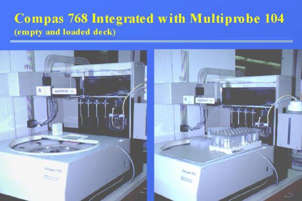 Figure 10 |
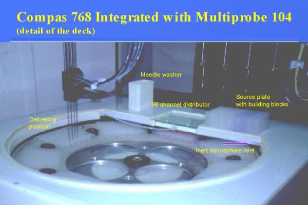 Figure 11 |
Since the goal of this instrument is its affordability in the laboratories with any size budget, we decided to design the system, which can be operated semi-manually and later upgraded to fully automated machine. Figure 12
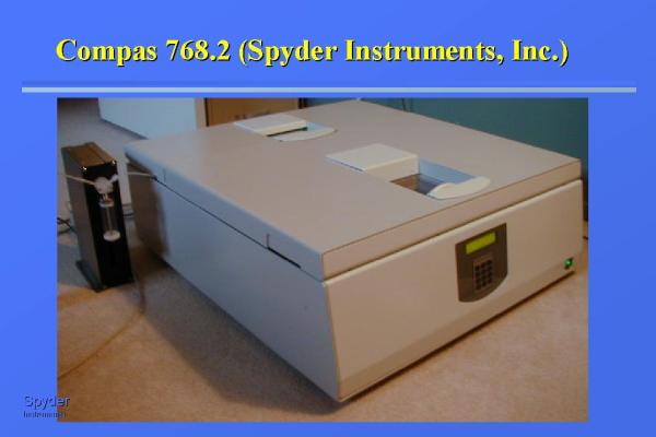 Figure 12 |
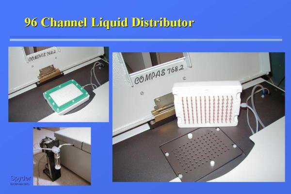 Figure 13 |
The synthesis is performed in the following way. Microtiterplate with slurry of solid support distributed into it is placed on the perimeter of a rotor with a permanent tilt of 9 degrees. The rotor is rotated at the speed required for complete removal of the liquid portion of the
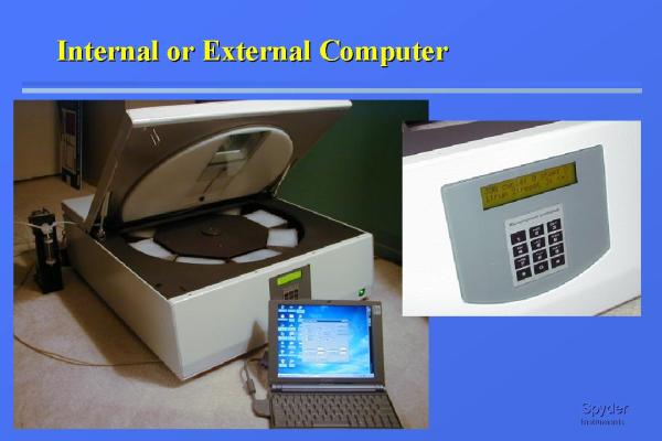 Figure 14 |
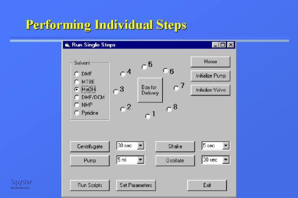 Figure 15 |
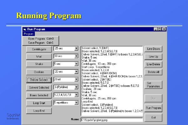 Figure 16 |
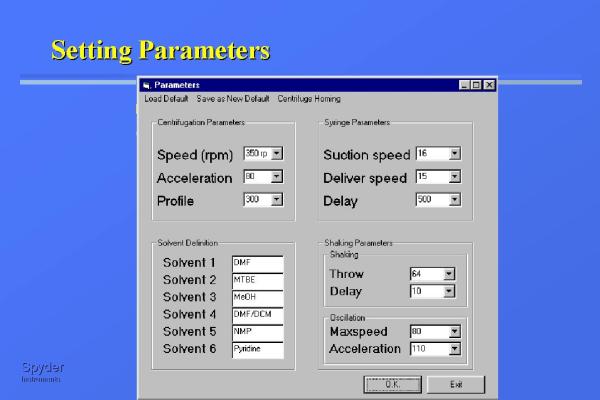 Figure 17 |
The best way to demonstrate the efficiency of the centrifugal synthetic technique is to show the results from the syntheses performed in the Compas 768. Figure 18 shows the synthetic scheme
 Figure 19 |
 Figure 18 |
We have synthesized hundreds of peptides and evaluated their cleavage from the resin by gaseous HF. Results from peptide syntheses are given in Figures 20 and 21. Figure 20 shows the results from the synthesis of tetrapeptides containing arginine. Figure 21 shows peptides composed of unnatural beta amino acids. Traces marked "a" contain products synthesized on benzhydrylamine resin and cleaved by two step process - in the first step the side chain protecting groups were removed by TFA and in the second step the product was cleaved from the resin by gaseous HF. Traces marked "b" contain products prepared on Knorr linker and cleaved in one step by TFA.
 Figure 20 |
 Figure 21 |
Conclusions
We believe that tilted centrifugation is the most effective and simplest method for liquid removal from multiplicity of vessels and polypropylene microtiterplates ideal reaction vessels for tilted centrifugation based synthesis. The fact that tilted centrifugation is the only way for removal of liquids from unlimited number of reaction vessels simultaneously is suggesting its application in ultraminiaturized synthesizers.
References
- Leblova Z, Lebl M. Compilation of papers in molecular diversity field. 2001. INTERNET World Wide Web address: http://www.5z.com/divinfo/.
- Merrifield RB. Solid phase peptide synthesis. I. The synthesis of a tetrapeptide. J.Amer.Chem.Soc. 1963;85:2149-54.
- Cargill JF, Lebl M. New methods in combinatorial chemistry: Robotics and parallel synthesis. Curr.Opin.Chem.Biol. 1997;1(1):67-71.
- Krchnák V, Weichsel AS, Lebl M, Felder S. Automated solid-phase organic synthesis in micro-plate wells. Synthesis of N-(alkoxy-acyl)amino alcohols. Bioorg.Med.Chem.Lett. 1997;7(8):1013-6.
- Lebl M, Krchnák V. Techniques for massively parallel synthesis of small organic molecules. In: Epton R, editor. Innovation and Perspectives in Solid Phase Synthesis & Combinatorial Libraries. Birmingham: Mayflower Scientific Limited; 1998.
For a version of this document without the embedded images please click here.